
Overlay and switch stack
Coordinate the graphic surface with the membrane circuit and tactile construction.
COORDINATED INTERFACE ASSEMBLIES
Coordinate the graphic interface, switching layers, tails, connectors, adhesive and optional support elements as one keypad assembly.
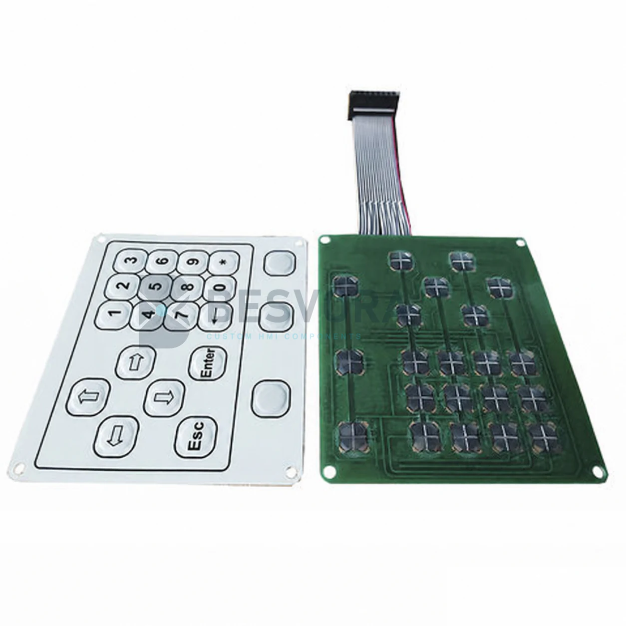
PRODUCT OVERVIEW
An integrated keypad assembly brings the visible interface and the functional switch structure into one coordinated component. Depending on the project, the scope may include graphic layers, membrane circuits, tactile elements, adhesive, tails, connectors, backlighting and selected support layers.
The purpose is not to claim a complete electronic controller. It is to organise the physical keypad layers and interfaces that connect the operator surface to the customer’s equipment.
Displays, control electronics, housings and final system certification are not included unless they are specifically defined in the project scope. Customer-equipment validation remains required.
STARTING INFORMATION
You do not need every answer before contacting us. Send what is available and the missing items can be identified during clarification.
Which layers and support elements should be supplied together.
Available space, mounting surface, openings and connection location.
Key action, indicators, illumination and any display or window areas.
Drawings, samples, photos, BOM references or interface specifications.
APPLICATIONS
Suitability depends on the final construction, equipment interface and customer validation.
COMMON QUESTIONS
No. The standard scope described here is the custom keypad and interface assembly, not the customer’s controller, software or complete enclosure.
They can be evaluated when their mechanical and electrical interfaces are defined as part of the assembly.
Yes. Existing samples and drawings can provide a starting point, followed by controlled prototyping and customer validation.
DISCUSS YOUR PROJECT
Start with a short description of keypad assemblies. Drawings or confidential files can be shared later through business email, WhatsApp or another agreed channel.