
Tail geometry
Define exit side, direction, length, bend zone and clearance.
MEMBRANE-SWITCH ENGINEERING OPTION
Match the circuit format, tail geometry, pinout, connector and support to the space and electrical interface inside the equipment.
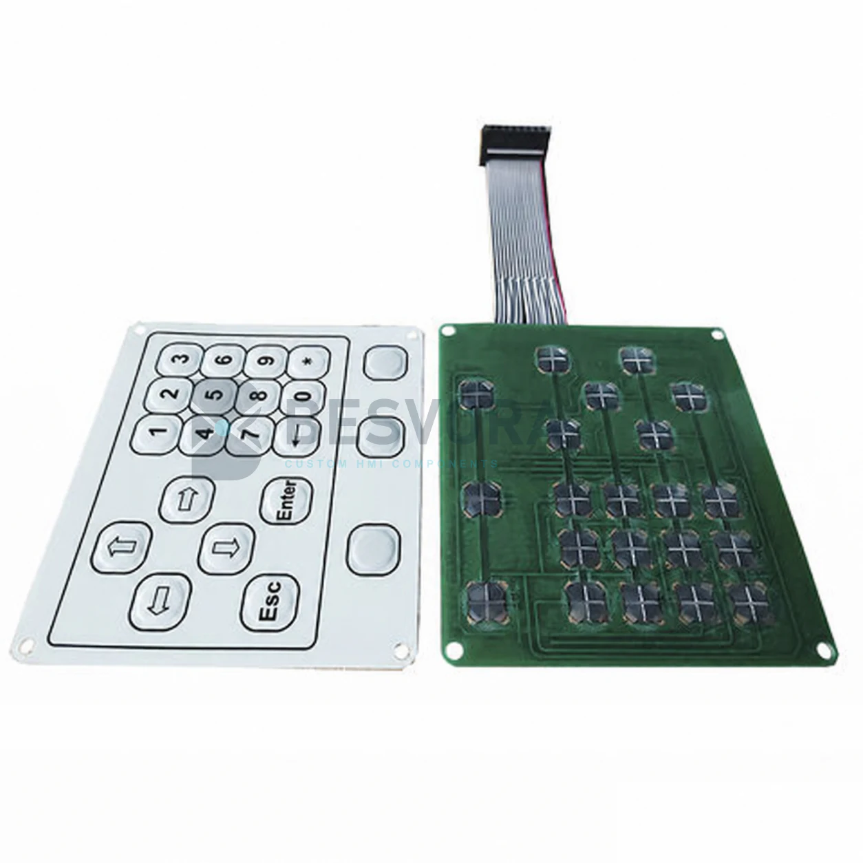
ENGINEERING OVERVIEW
The switch circuit and tail carry the key matrix from the operator interface to the customer electronics. Exit direction, bend area, pitch, pinout, connector, stiffener and available clearance need to be coordinated with the enclosure and assembly sequence.
Where the project needs a different circuit format or support, an FPC or PCB-based interface can be reviewed as part of the agreed keypad-assembly boundary.
Circuit format, conductor design, current limits, connector compatibility and assembly clearances are confirmed from the controlled project drawing. Customer controller design and final electrical safety remain outside the component scope unless expressly included.
STARTING INFORMATION
You do not need every answer before contacting us. Send what is available and the missing points can be identified during clarification.
Required circuits, common lines, contact order and any existing schematic.
Part reference, mating interface, insertion direction and available height.
Tail exit, bends, enclosure openings and assembly sequence.
Signal type and any project-specific limits or test requirements.
POSSIBLE APPLICATIONS
Suitability depends on the final construction, equipment interface and customer validation.
COMMON QUESTIONS
Yes. They are reviewed with the pinout, contact pitch, enclosure route and customer mating interface.
A different circuit or support format may be evaluated when routing density, component integration, connection or mechanical support requires it.
DISCUSS YOUR PROJECT
Start with a short description of fpc, pcb & custom tails. Drawings or confidential files can be shared later through business email, WhatsApp or another agreed channel.