
Shield coverage
Define the area and relationship between the conductive layer, keys, windows and circuit.
MEMBRANE-SWITCH ENGINEERING OPTION
Coordinate the shield layer and grounding route with the membrane circuit, tail, enclosure and the customer’s complete EMC design.
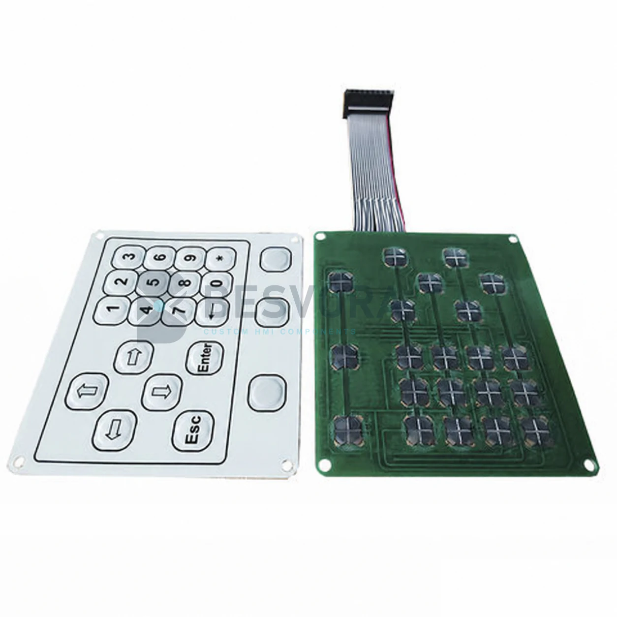
ENGINEERING OVERVIEW
A membrane interface may include a conductive shield layer or grounding feature to support an EMI or ESD strategy. The useful design depends on where interference or discharge may enter, how the shield is connected and how the enclosure and electronics are grounded.
The layer stack, shield coverage, tail routing and connection point therefore need to be reviewed with the customer’s electrical and mechanical design.
A shielded membrane switch does not by itself establish system EMC compliance. Effectiveness and regulatory performance require testing in the defined customer assembly.
STARTING INFORMATION
You do not need every answer before contacting us. Send what is available and the missing points can be identified during clarification.
The ESD or EMI issue, test requirement or observed failure to be addressed.
Ground reference, connector, circuit and controller information relevant to the interface.
Enclosure material, openings, stack and available grounding area.
Applicable component checks and complete-equipment EMC tests.
POSSIBLE APPLICATIONS
Suitability depends on the final construction, equipment interface and customer validation.
COMMON QUESTIONS
No. Shielding is one design element; grounding, enclosure, cabling, electronics and system testing remain essential.
They can be reviewed against the circuit, openings, tail route and customer grounding design.
DISCUSS YOUR PROJECT
Start with a short description of emi & esd shielding. Drawings or confidential files can be shared later through business email, WhatsApp or another agreed channel.